Arduino

An Arduino is Open-source electronic prototyping platform enabling users to create interactive electronic objects. - Arduino.cc. To get a better understanding about what's possible to use as an input or output device, me and my fellow student where able to learn the basics of prototyping with an Arduino with multiple sensors, lights, resistors, wires and other small electronics. To summaries what I have learned from these workshops, I put a few of the assignments on this page.

Assignments

Here is a summary of the assignments I did during the workshops.

2: FADE LED - ANALOG OUTPUT

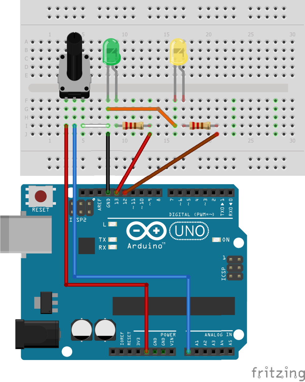
A lot more is possible than to just put a LED on and off. With the analog write function you can make the LEDs fade in and out. In this example the objective was to make the green LED fade in while the yellow LED fades out.

Circuit layout of Fade LED Analog Output assignment
int greenLedPin = 10;
int yellowLedPin = 9;
void setup() {
	pinMode(greenLedPin, OUTPUT);
	pinMode(yellowLedPin, OUTPUT);
}
void loop() {
	 for (int brightness=0; brightness <256; brightness++){
		analogWrite(greenLedPin, brightness);
		analogWrite(yellowLedPin, 255 - brightness);
		delay(10);
	}
}

3: CONTROLLING A LED WITH A POTMETER

It's also possible to control the LEDs with a potentiometer. By putting a current through the potmeter and connecting it to the Arduino we can read its value. Then it's possible to use this value to control the LED.

Circuit layout of Controlling a LED with a potmeter assignment
float sensorValue = 0;
int sensorPin = A0;
int greenLedPin = 10;
void setup() {
	Serial.begin(9600);
	pinMode(sensorPin, INPUT);
	pinMode(greenLedPin, OUTPUT);
}
void loop() {
	sensorValue = analogRead(sensorPin);
	sensorValue = (sensorValue/1023)*255;
	analogWrite(greenLedPin, sensorValue);
	Serial.println(sensorValue);
	delay(100);
}

4: CONTROL THE LED WITH LIGHT

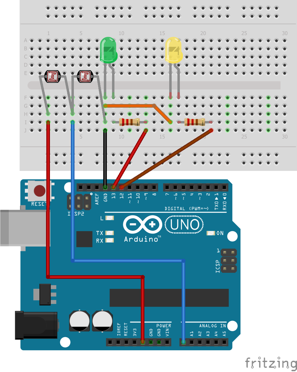
A Light-Dependent Resistor or LDR is, as the name suggests, a resistor that has its resistance depending on the amount of light it's relieving. So, in complete darkness the LDR's resistance is about 5,000,000ohm or 5megohm and with a very bright light shining on it it's about 200ohm. By mapping the output of this sensor, we can control the LED.

Circuit layout of Control the LED with light assignment
float sensorValue = 0;
int sensorPin = A0;
int greenLedPin = 10;
int yellowLedPin = 9;
void setup() {
	pinMode(sensorPin, INPUT);
	Serial.begin(9600);
	pinMode(greenLedPin, OUTPUT);
	pinMode(yellowLedPin, OUTPUT);
}
void loop() {
	sensorValue = analogRead(sensorPin);
	Serial.println(sensorValue);
	sensorValue = map(sensorValue, 550, 795, 255, 0);
	analogWrite(greenLedPin, sensorValue);
	analogWrite(yellowLedPin, sensorValue);
	delay(200);
}

5: VOLTAGE DIVIDER

This exercise used the same code as the previous one. The only difference to the breadboard is that a resistor was replaced with another LDR. In this assignment we needed to explain what happens when the resistor is replaced.

Circuit layout of Voltage devider assignment
float sensorValue = 0;
int sensorPin = A0;
int greenLedPin = 10;
int yellowLedPin = 9;
void setup() {
	pinMode(sensorPin, INPUT);
	Serial.begin(9600);
	pinMode(greenLedPin, OUTPUT);
	pinMode(yellowLedPin, OUTPUT);
}
void loop() {
	sensorValue = analogRead(sensorPin);
	Serial.println(sensorValue);
	sensorValue = map(sensorValue, 550, 795, 255, 0);
	analogWrite(greenLedPin, sensorValue);
	analogWrite(yellowLedPin, sensorValue);
	delay(200);
}

We can calculate what happens with this formula:

Vout = Vin * R2:(R1 * R2) = Vout

For example, we can fill in this formula with different light inputs to calculate the voltage output.

Left resistor in the dark and right resistor in the light:

R1 = 5megohm
R2 = 200ohm
Vin = 5v
5v * 200ohm : (5megohm + 200ohm) = ~0v

Left resistor in the light and right resistor in the dark:

R1 = 200ohm
R2 = 5megohm
Vin = 5v
5v * 5megohm : (200ohm + 5megohm) = ~5v

Both resistors in the light:

R1 = 200ohm
R2 = 200ohm
Vin = 5v
5v * 200ohm : (200ohm + 200ohm) = 2.5v

Both resistors in the dark:

R1 = 5megohm
R2 = 5megohm
Vin = 5v
5v * 5megohm : (5megohm + 5megohm) = 2.5v

6: ARDUINO AND PROCESSING

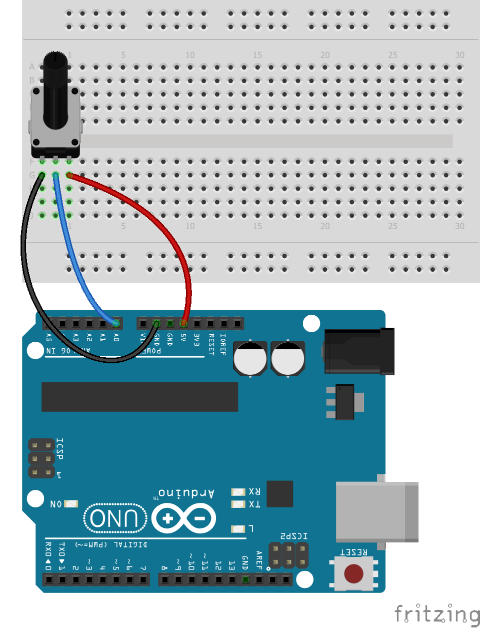
Another interesting assignment we had to do was this one. By connecting the Arduino to my computer, I was able to write a small program that used the potmeter to control a shape on my screen. I used a program called processing and used is to make a rectangle jump around and change color from blue to red and back by turning the potmeter physically.

Circuit layout of Arduino and Processing assignment
float sensorValue = 0;
int sensorPin = A0;
void setup() {
	pinMode(sensorPin, INPUT);
	Serial.begin(9600);
}
void loop() {
	sensorValue = analogRead(sensorPin);
	sensorValue = map(sensorValue, 0, 1023, 255, 0);
	Serial.println(sensorValue);
}
import processing.serial.*;
Serial myPort;
String sensorReading="";
void setup() {
	size(400, 400);
	myPort = new Serial(this, Serial.list()[2], 9600);
	myPort.bufferUntil('\n');
}
void draw() {
	background(255);
	fill(float(sensorReading),0,255-float(sensorReading));
	noStroke();
	text("Sensor Reading: " + sensorReading, 20, 20);
	rect(map(float(sensorReading),0,255,0,200),map(sin(float(sensorReading)/10),0,1,100,120), 200, 200);
}
void serialEvent (Serial myPort) {
	sensorReading = myPort.readStringUntil('\n');
}

7: BUTTONS

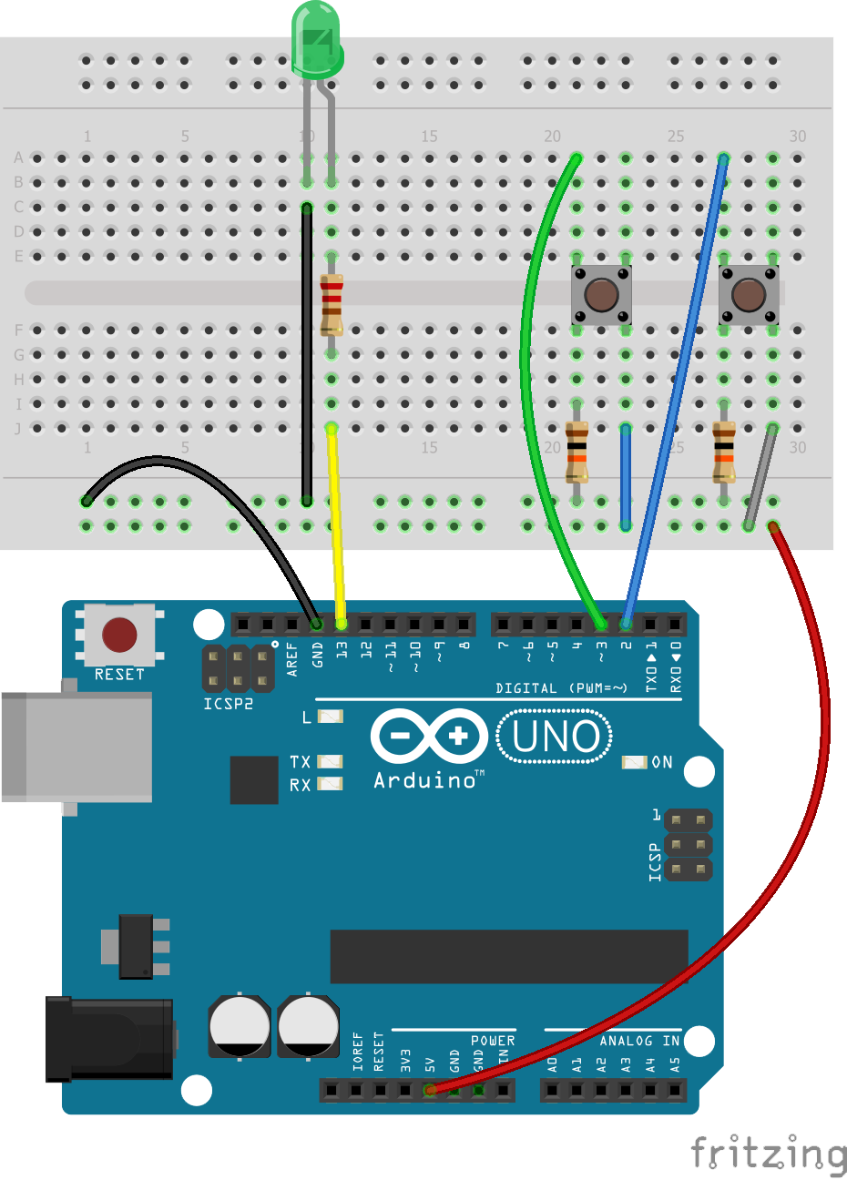
By putting two buttons on my breadboard and connecting them to my Arduino I created two interaction inputs. The task in this assignment was to only make the LED light up when one button is pressed. Using a condition that checked if both input pins have a different voltage, I made the code as short as possible. I could have made the code more readable by adding variable names but decided to challenge my self to make it as efficient as possible.

Circuit layout of buttons assignment
void setup() {
	pinMode(13, OUTPUT);	//LED pin
	pinMode(3, INPUT);		//Left button pin
	pinMode(2, INPUT);		//right button pin
}
void loop(){
	if (digitalRead(2) != digitalRead(3)) {
		digitalWrite(13, HIGH);  
	} else {
		digitalWrite(13, LOW);
	}
}

8: SERVOMOTOR

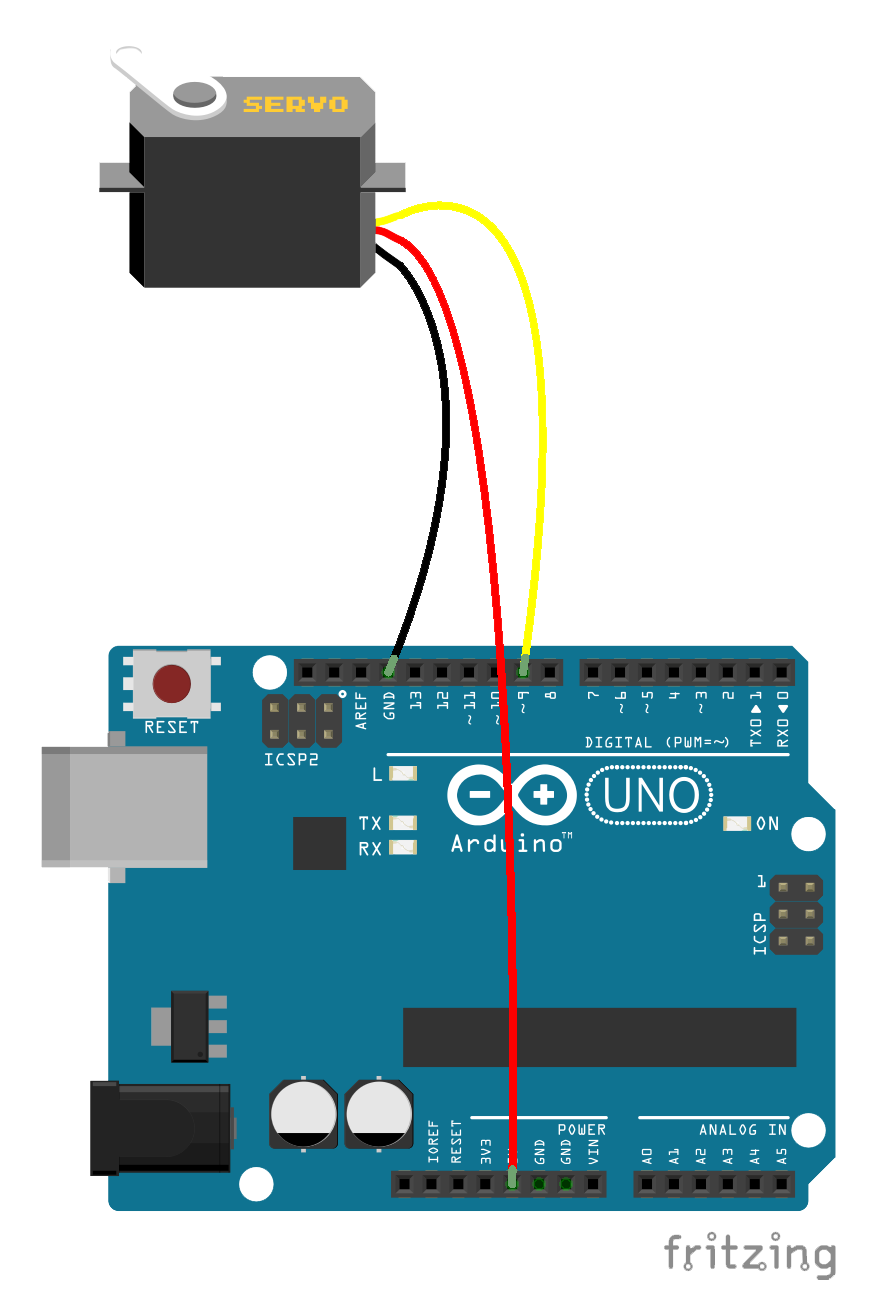
In this exercise where we got the task to let the servo dance. I did this by setting differed positions and added a for loop that iterated through positions. When I uploaded the code, it did its dance and by doing so I learned how to control a servo with an Arduino.

Circuit layout of servomotor assignment
#include <Servo.h>
Servo myServo;
int servoPin = 9;
int pos = 0;
void setup() {
	myServo.attach(servoPin);
}
void loop() {
	myServo.write(0);
	delay(500);
	myServo.write(160);
	delay(500);
	myServo.write(80);
	delay(500);
	myServo.write(160);
	delay(500);
	myServo.write(0);
	delay(500);
	for(pos = 0; pos < 160; pos += 1){
		myServo.write(pos);
		delay(15);
	}
}

9: CONTROLLING THE SERVO WITH INPUTS

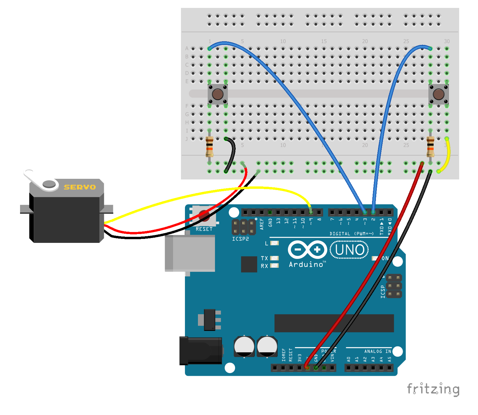
Radio controlled cars, boats and planes use servos to control steering, pitch, roll and/or yaw. In this exercise I added to buttons to control a servo. By doing so, I could implement this in radio controlled vehicles in the future. The servo I used could only rotate from 0 to 160 degrees, so I added an if statement to check is the value was between these positions before executing the movements.

Circuit layout of controlling the servo with inputs assignment
#include <Servo.h>
Servo myServo;
int servoPin = 9;
int pos = 0;
int buttonPinL = 3;
int buttonPinR = 2;
void setup() {
	myServo.attach(servoPin);
	pinMode(buttonPinL, INPUT);
	pinMode(buttonPinR, INPUT);
}
void loop() {
		if (digitalRead(buttonPinL) == HIGH && digitalRead(buttonPinR) == LOW){
			pos++;
			if (pos > 160) {
				pos = 160;
			}
		 	delay(15); 
		}
		if (digitalRead(buttonPinR) == HIGH && digitalRead(buttonPinL) == LOW){
			pos--;
			if (pos < 0) {
				pos = 0;
			}
			delay(15);
		}
		if (pos >= 0 && pos <= 160) {
			myServo.write(pos);
		}
}

10: SOUND

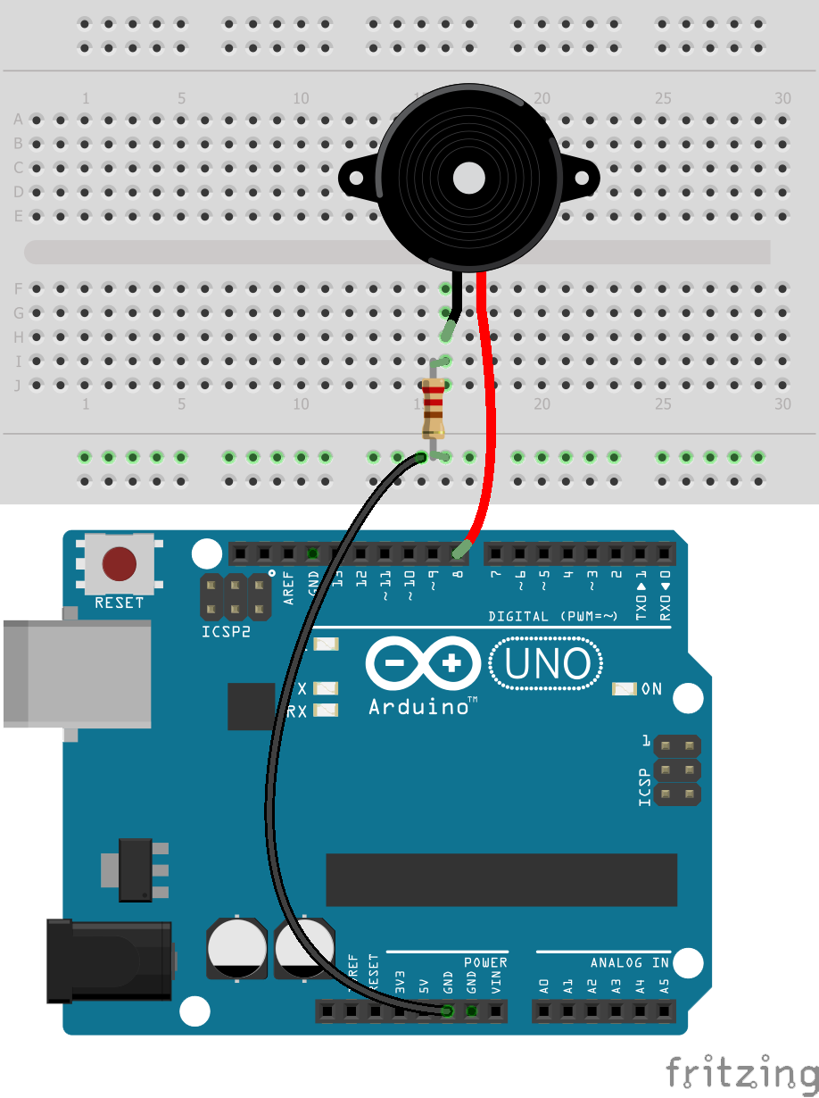
Now it was time for some jams. With the buzzer connected to the Arduino I was able to create some tunes. The tone function was used to set the speaker pin, the amount of Hz and the duration. Unfortunately, I lost the original code I used when I was recording the video but it was something like the one below.

Circuit layout of the sound assignment
int speakerPin = 8;
void setup() {
  pinMode(speakerPin, OUTPUT);
}
void loop() {
	for (int i = 0; i < 8; i ++) {
		tone(speakerPin, 1046, 100);
		delay(1000); 
	}
	for (int i = 0; i < 12; i ++) {
		tone(speakerPin, 1046, 100);
		delay(500); 
	}
	for (int i = 0; i < 12; i ++) {
		tone(speakerPin, 1046, 100);
		delay(250); 
	}
	for (int i = 0; i < 12; i ++) {
		tone(speakerPin, 1046, 100);
	 	delay(125); 
	}
	for (int i = 1046; i > 200; i--){
		tone(speakerPin, i);
		delay(10);
	}
	tone(speakerPin, 3000);
	delay(8000);
}

WARNING! Headphone users must lower their volume!